-
English


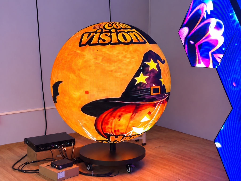
Before calibrating a fine-pitch spherical LED display, inspect its surface with the screen switched off. A raised module edge or uneven joint is a physical problem. Brightness adjustments cannot move that edge back into position.
On a sphere, “flatness” means checking whether neighboring modules follow the intended surface profile. The goal is a consistent transition across each seam, while keeping the designed curvature.
This spherical LED display flatness test provides a practical inspection sequence before final brightness and color calibration.
Separate three conditions that can look similar during playback:
These conditions need different adjustments. Closing a gap will not necessarily correct a raised edge.
Fine-pitch screens deserve close inspection because a small spacing error can represent a noticeable fraction of the pixel pitch. However, pixel pitch alone does not define the acceptable mechanical tolerance. Use the approved assembly drawing and manufacturer’s inspection requirements.
Complete the inspection in the intended mounting orientation, with the support structure secured. A temporary position may load the frame differently from the final installation.
Give each suspect joint a reference using the module numbers. Record whether it is a vertical seam, horizontal seam, or intersection.
Use a movable inspection light at a shallow angle to the surface. Sweep it across each joint from opposite directions. A raised edge may create a narrow shadow that changes when the light moves.
Check the equator, upper and lower sections, and module corners. A joint that looks even at its center may still have a lifted corner.
Treat shadows as clues, then confirm them through measurement.
A long straight ruler cannot establish whether a spherical surface is correct. The intended curve naturally leaves space beneath it.
Instead, use a manufacturer-approved profile template or measurement fixture matched to the local design. A smoothly curved module and a faceted assembly require different reference profiles.
Where contact measurement is permitted, reference designated mechanical surfaces. Do not drag metal tools across LED packages or press the emitting surface.
Measure suspect joints at both ends and the midpoint. Record seam width and edge step separately. For tapered modules, compare the results with the local drawing dimensions; do not assume every joint should have identical spacing.
If several neighboring seams show the same mismatch, inspect the supporting frame before adjusting individual modules. Wider assembly errors may require a structural check, as explained in our guide to spherical LED display tolerance stack-up.
After the physical inspection, power on the display using the manufacturer’s test procedure. Keep brightness and processing settings unchanged while comparing views.
Show a uniform mid-gray field, followed by a grid prepared for the sphere’s pixel map.
Inspect each marked seam from:
Watch how the line changes. A seam that becomes much stronger from one side deserves another mechanical inspection. A broad brightness difference across an entire module also warrants electrical and calibration checks.
Viewing angle alone cannot identify the cause. LED viewing characteristics can also change the appearance, so combine this check with the screen-off findings.
For grid patterns, inspect continuity across the joint against the expected mapping. Do not expect a flat rectangular grid to appear straight everywhere on a sphere.
Possible causes include incomplete module seating, debris at mounting points, trapped cables, inconsistent support height, or a distorted bracket.
Power down before mechanical adjustment. Follow the approved removal and fastening procedure. Do not force a module into place or tighten fasteners beyond specification.
After adjustment, inspect the repaired joint and its neighbors. Moving one module may improve one seam while disturbing another.
For a hypothetical showroom installation, a vertical line might appear acceptable head-on but become obvious from the visitor entrance. If inspection confirms a lifted corner, reseating that module addresses the cause before calibration begins.
Use a simple inspection record:
| Check | Record |
|---|---|
| Location | Module IDs and joint position |
| Geometry | Seam width, edge step, profile result |
| Viewing | Front, left, and right observations |
| Rework | Adjustment and neighboring seams checked |
Accept the geometry against agreed project tolerances. Then repeat the visual check under normal operating conditions after the specified warm-up. Keep photographs at consistent positions and exposure settings for comparison.
Some systems can reduce certain visible seam effects. They cannot physically correct a raised edge, distorted support, or incorrect module position.
No. Limits depend on the module construction, surface geometry, and project requirements. Agree on measurable criteria before assembly.
TOOSEN supplies spherical LED displays in different diameters and pixel pitches, with technical support and installation guidance. Share your viewing distance, mounting method, and sphere dimensions, and request an agreed seam inspection procedure before final calibration.
+86 18688923792
+86-755-23312336
4th Floor, Building B, Zhonghe Building, Taiwan Industrial Zone, 2132 Songbai Road, Shiyan Street, Bao'an District, Shenzhen.


Emall us with any questions or inquiries or use our contact data.We would be happy to answer your questions.
Toosen Professional Manufacturer of led sphere display,led screen globe,led ball display,spheric led screen,spherical led display, Led Special-shaped LED manufacturer, LED factory,Manufacturers & Suppliers,Factory & Exporters. Looking forward to your cooperation.
Copyright © 2010-2026 Toosen LED All Rights Reserved
Theme by WordPress