-
English


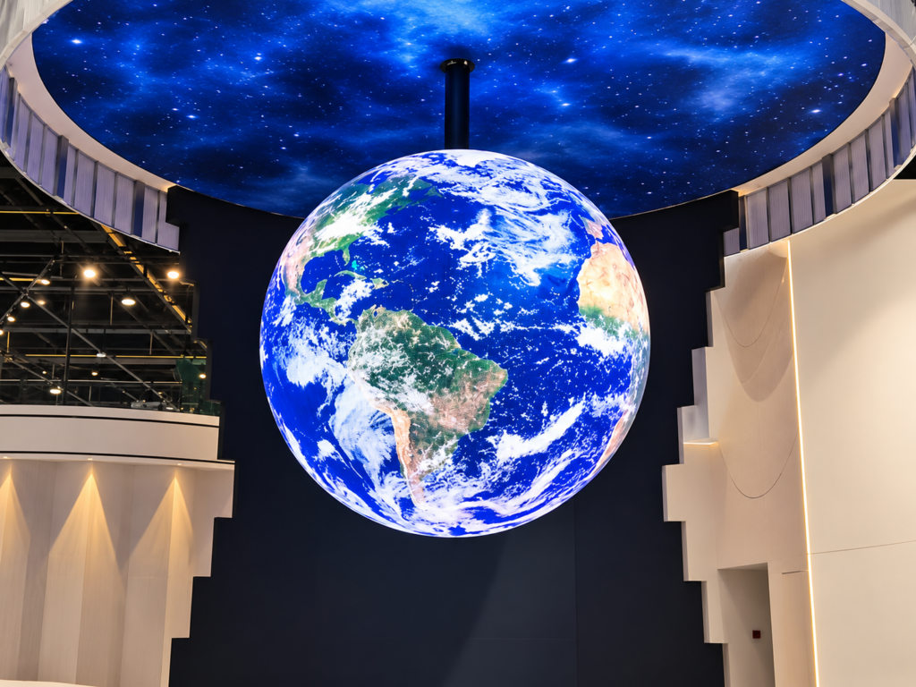
An LED ball display may need to rotate, move between preset positions, or work with a mechanical lifting system. In these projects, reaching the correct position once is not enough. The display must return to the same position after repeated movement.
For example, a rotating LED ball used at a trade show may need to stop at a fixed angle before showing a product logo. If the ball stops at a slightly different angle each time, the logo may appear in the wrong direction. The problem becomes more noticeable when the display works with lighting, cameras, or other stage equipment.
Positioning accuracy and repeatability are related but different. Accuracy measures how close the final position is to the target. Repeatability measures how consistently the system returns to the same position under similar conditions.
Both should be checked before a moving LED display is accepted.
Small positioning errors can affect the entire presentation.
First, content may not face the intended viewing area. A logo or graphic that should face the audience may stop slightly off-center.
Second, the display may lose coordination with other equipment. If a rotating screen must stop at a specific angle for a camera shot or lighting effect, inconsistent stopping positions can disrupt the sequence.
Third, repeated movement may reveal mechanical problems that are not obvious during a short demonstration. Loose connections, backlash, uneven loads, and changing friction can affect the final position.
These problems can increase commissioning time and require repeated adjustments on site. A positioning test helps identify them before handover.
Several factors can affect an LED ball display’s repeatability.
Motor and drive system: A motor may not stop at exactly the same point because of control settings, braking behavior, or changes in load.
Mechanical backlash: Gaps between gears or drive components can cause different final positions depending on the direction of movement.
Load imbalance: An unevenly distributed load can change the force required to move or stop the display.
Encoder or reference errors: Incorrect feedback, a poorly defined home position, or a shifted reference sensor can produce inconsistent readings.
Structural movement: Loose mounting points, vibration, or frame deformation may affect the relationship between the mechanical reference and the display surface.
The first step is to determine whether the error comes from the control system, the mechanical structure, or the reference measurement.
Before testing, confirm that the display is installed securely and that the movement system operates within its approved limits.
Set a clear reference position. This could be a verified encoder position, a mechanical home point, or another suitable reference specified by the system designer. Do not rely only on a visual estimate.
Check the motor, drive connections, mounting hardware, and relevant feedback devices. Confirm that acceleration, deceleration, and stopping settings match the intended operating conditions.
If the system approaches a target from different directions, test both directions separately. Mechanical backlash may cause different results when the drive reverses.
Record the original settings before making adjustments. Change one parameter at a time so that the effect of each adjustment can be identified.
Never increase the load or bypass safety controls simply to reproduce a positioning error.
A repeatable test should use the same target positions, movement sequence, and measurement method throughout the inspection.
Select a target angle or position and record its nominal value. Confirm that the measuring instrument or encoder has been checked and that the reference remains fixed throughout the test.
For a rotating display, a calibrated angle measurement or suitable position-feedback system is preferable to judging alignment by eye.
Move the LED ball display from its starting position to the target. Allow the system to stop and settle before recording the final position.
Repeat the movement in the same direction to establish an initial result.
Run a series of identical movement cycles under normal operating conditions. For example, a project team could use 30 cycles as an initial screening test, provided this is suitable for the equipment and project requirements.
For each cycle, record the target position, measured final position, movement direction, and any unusual vibration or noise.
The number of cycles and allowable error should be agreed upon before testing. Thirty cycles is an example, not a universal acceptance standard.
For each measurement:
Positioning error = Measured position − Target position
If the target is 90° and the measured position is 90.4°, the error is +0.4°.
Compare the results across all cycles. The average error shows whether the system tends to stop before or beyond the target. The difference between the highest and lowest readings indicates the spread of results.
For angular measurements that cross 0°, normalize the angles before calculating errors.
Repeat the test at other required target positions. If the system operates in both directions, compare clockwise and counterclockwise approaches.
Where approved, repeat the test after normal operating warm-up and under representative working loads. Record any changes rather than combining different test conditions into one result.
After the mechanical test, display a clear reference pattern or numbered graphic. Confirm that the intended content faces the correct viewing direction when the system stops.
This additional check helps distinguish mechanical positioning errors from content-mapping problems.
A complete inspection may include the motor, gearbox, encoder, home-position sensor, controller, mounting frame, bearings, and relevant electrical connections.
The exact components depend on the movement design. A fixed LED ball display does not require the same positioning test as a motorized or lifting system.
Toosen supplies customized spherical LED displays in different diameters and pixel pitches, with installation options including hanging, floor-standing, and customized structures. For projects involving mechanical movement, the motion system and its acceptance criteria should be specified separately from the LED display’s visual performance.
Consider an exhibition project in which an LED ball must stop at three preset angles to present different branded graphics.
During commissioning, the installation team records each target angle and repeats the movement sequence. The results show that the first position is consistent, but the third position has a wider range of stopping errors.
The team then checks the drive direction, mechanical connections, and position feedback. After identifying and correcting the cause, it repeats the same test using the original measurement method.
The project should be accepted only when the recorded results meet the agreed positioning tolerance and the graphics face the intended viewing areas.
This approach provides measurable evidence instead of relying on a successful single demonstration.
Q1: What is a good positioning tolerance for an LED ball display?
There is no single tolerance for every project. It depends on the display size, movement mechanism, visual requirements, and application. Define the acceptable error with the equipment supplier before testing.
Q2: How many movement cycles should be tested?
The test plan should reflect the expected operating frequency and project risk. Thirty cycles can be used for an initial screening test, but more cycles may be required for demanding applications.
Q3: Does a repeatability test replace a safety test?
No. Positioning repeatability checks whether the system returns to the expected position. Mechanical load capacity, emergency stops, guarding, and other applicable safety requirements need separate verification.
Q4: Can software calibration solve every positioning problem?
No. Calibration may correct certain control or reference errors, but it cannot reliably solve loose hardware, excessive backlash, structural movement, or other underlying mechanical faults.
A reliable LED ball display project needs more than good image quality. When movement is part of the design, the mechanical system must also deliver consistent and verifiable results.
Before shipment, agree on the target positions, test conditions, measurement method, cycle count, and allowable error. Keep the test records so the installation team can compare factory results with on-site performance.
Toosen supports customized spherical LED display projects for exhibitions, shopping malls, stage environments, and other commercial applications. Defining positioning requirements early helps buyers, engineers, and installers work toward the same acceptance criteria and reduces avoidable adjustments during commissioning.
+86 18688923792
+86-755-23312336
4th Floor, Building B, Zhonghe Building, Taiwan Industrial Zone, 2132 Songbai Road, Shiyan Street, Bao'an District, Shenzhen.


Emall us with any questions or inquiries or use our contact data.We would be happy to answer your questions.
Toosen Professional Manufacturer of led sphere display,led screen globe,led ball display,spheric led screen,spherical led display, Led Special-shaped LED manufacturer, LED factory,Manufacturers & Suppliers,Factory & Exporters. Looking forward to your cooperation.
Copyright © 2010-2026 Toosen LED All Rights Reserved
Theme by WordPress