-
English


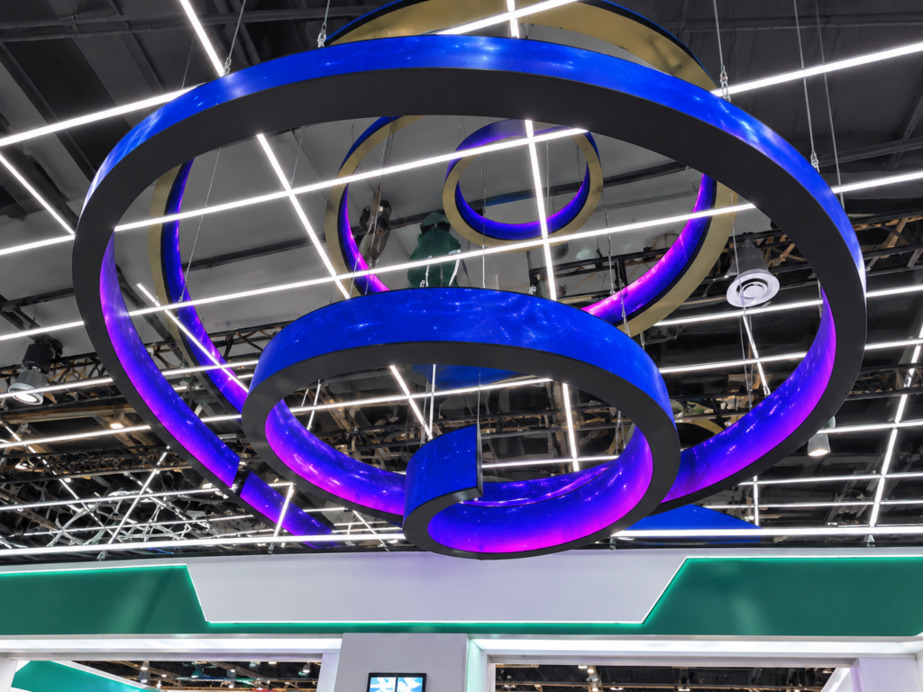
A flexible LED display may work normally during factory testing but experience signal interruptions after installation. The screen may suddenly go black, display incomplete images, flicker, or lose communication with several receiving cards.
When fiber optic transmission is used, these problems may come from the optical cable, connectors, optical transceivers, or incorrect system configuration.
Unlike traditional copper network cables, fiber optic cables transmit data through light. This makes them suitable for long-distance transmission and environments with strong electromagnetic interference.
However, fiber optic transmission still depends on clean connections, compatible equipment, and correct installation.
Finding the actual fault is important before replacing expensive control components.
An unstable fiber optic connection can affect more than one section of an LED display.
Common symptoms include:
For a large flexible LED display, these problems can interrupt advertising, presentations, live events, and other scheduled activities.
If the display uses a daisy-chain transmission structure, one failed connection may also affect downstream sections.
Dust, fingerprints, and small particles can contaminate fiber optic connector surfaces.
Even a small amount of contamination may increase optical loss and weaken the transmitted signal.
This problem is common when cables are frequently connected or disconnected during installation.
Fiber optic cables have specific bending limits.
If an installer forces a cable around a narrow corner or tightly ties it inside a curved display structure, excessive bending may increase signal attenuation.
Damaged cable jackets, crushed sections, and internal fiber breaks can also interrupt transmission.
Fiber optic systems normally use separate transmitting and receiving channels.
If the transmitting and receiving fibers are connected incorrectly, communication may fail.
This can happen when technicians reconnect cables after transportation or maintenance without checking the original connection arrangement.
The optical transceiver converts electrical signals into optical signals and converts received light back into electrical data.
Different transceivers may use different wavelengths, transmission distances, data rates, and connector types.
If the sending and receiving devices are incompatible, the signal may become unstable or fail completely.
A connector that is not fully inserted may create an unstable optical connection.
Repeated installation, vibration, and transportation can also damage connector housings or locking mechanisms.
Therefore, both ends of the fiber optic cable should be inspected.
A systematic inspection is more effective than replacing components randomly.
First, identify the complete signal path:
Video Source → LED Video Processor → Sending Card → Fiber Optic Transmitter → Fiber Cable → Optical Receiver → Receiving Cards → LED Modules.
Check the status indicators on the sending card and optical transmission equipment.
If the transmitter shows no output, inspect the upstream video signal and control equipment.
If the transmitter works but the receiver shows no optical link, focus on the fiber cable, connectors, and transceiver compatibility.
Disconnect the equipment according to the manufacturer’s maintenance procedure.
Use a suitable fiber inspection microscope to check the connector end faces.
Look for:
Clean contaminated connectors with compatible fiber-optic cleaning tools.
Never look directly into an optical fiber or optical transmitter, as invisible laser light may cause eye injury.
Flexible LED displays often have curved structures, narrow internal spaces, and complicated cable routes.
Inspect whether the fiber cable is crushed, tightly bent, or pulled against its connector.
Make sure the cable follows the manufacturer’s minimum bending radius.
If necessary, temporarily replace the suspected cable with a known-good fiber cable to compare the results.
Check whether the transmitting port connects to the receiving port at the opposite end.
For duplex fiber connections, confirm that the two optical paths are not reversed.
Also verify that the optical modules at both ends support the same transmission requirements.
A fiber optic power meter provides a more accurate way to identify signal attenuation.
Measure the optical power at the receiving end and compare it with the transceiver manufacturer’s specified operating range.
If the received power is below the acceptable level, inspect the connectors, cable condition, connection points, and transmission equipment.
An optical loss test can also help identify excessive attenuation along the complete fiber link.
After correcting the connection problem, do not immediately return the display to normal operation.
A complete verification should include:
Record the measured optical power, cable identification, transceiver model, and test results. This information makes future maintenance easier.
A stable flexible LED display transmission system depends on several components working together.
The cable route should also be planned together with the flexible LED display’s mechanical structure. This helps prevent excessive bending, connector tension, and difficult maintenance access.
Consider a large curved LED display installed in a shopping mall.
The control room is located some distance away from the display, so the project uses fiber optic transmission.
After installation, several screen sections occasionally lose their images.
The technicians first check the sending card and receiving cards. Their status indicators suggest that the control system is operating.
Further inspection reveals contamination on one fiber connector. The optical power measurement also shows that the received signal is weaker than expected.
After cleaning the connector, checking Tx/Rx polarity, and reconnecting the fiber cable, the optical power returns to the acceptable operating range.
The display then passes a continuous playback test without further signal interruptions.
This example shows why checking the optical transmission path before replacing LED modules or receiving cards can save maintenance time.
Q1: Why does my flexible LED display suddenly show no signal?
Possible causes include dirty fiber connectors, damaged optical cables, incorrect Tx/Rx connections, incompatible transceivers, or a faulty sending or receiving card.
Q2: Can a dirty fiber optic connector cause LED screen flickering?
Yes. Contamination can increase optical loss and make the transmission link unstable, resulting in intermittent image interruptions.
Q3: How can I check whether a fiber optic cable is damaged?
Inspect the cable jacket and routing, check the connector end faces, and use suitable optical testing equipment to measure continuity and signal loss.
Q4: Does fiber optic transmission prevent electromagnetic interference?
Fiber carries data through light rather than electrical signals, so it is highly resistant to electromagnetic interference along the optical link. However, the surrounding control equipment and power connections still require proper electrical design.
Q5: How often should fiber optic connectors be cleaned?
Inspect connectors whenever they are disconnected or reconnected. Clean them when contamination is detected, following the connector and equipment manufacturer’s instructions.
Q6: Is fiber optic transmission suitable for long-distance flexible LED displays?
Yes. Fiber optic transmission is suitable for many long-distance LED display projects. The actual transmission distance depends on the fiber type, transceiver specifications, wavelength, and optical link budget.
A reliable flexible LED display requires more than high-quality LED modules. Signal transmission, connector quality, cable routing, receiving cards, and control system compatibility all contribute to stable operation.
Toosled provides customized LED display solutions for curved surfaces, columns, spheres, and other special-shaped installations.
With project-specific structural design, system configuration, and production testing, we help customers address different installation and operating requirements.
Whether your project requires a flexible LED screen for a shopping mall, exhibition hall, stage, or commercial space, contact Toosled to discuss the appropriate display structure and transmission solution.
+86 18688923792
+86-755-23312336
4th Floor, Building B, Zhonghe Building, Taiwan Industrial Zone, 2132 Songbai Road, Shiyan Street, Bao'an District, Shenzhen.


Emall us with any questions or inquiries or use our contact data.We would be happy to answer your questions.
Toosen Professional Manufacturer of led sphere display,led screen globe,led ball display,spheric led screen,spherical led display, Led Special-shaped LED manufacturer, LED factory,Manufacturers & Suppliers,Factory & Exporters. Looking forward to your cooperation.
Copyright © 2010-2026 Toosen LED All Rights Reserved
Theme by WordPress