-
English


A spherical LED display may work perfectly during factory testing but show occasional flickering, black sections, or signal interruptions after it is installed at the project site.
When this happens, people often check the LED modules, receiving cards, controller, and power supplies first. These are important checks, but there is another factor that should not be ignored: signal cable length.
For a normal flat LED wall, signal cables usually follow relatively simple rows and columns. A spherical LED display is different. Its modules and receiving cards are distributed around a three-dimensional structure, which can make the actual signal path longer and more complicated.
Understanding this difference helps engineers build a more stable spherical LED display control system.
In a typical LED display system, image data follows a basic path:
Video Source → LED Controller → Signal Cable → Receiving Cards → LED Modules
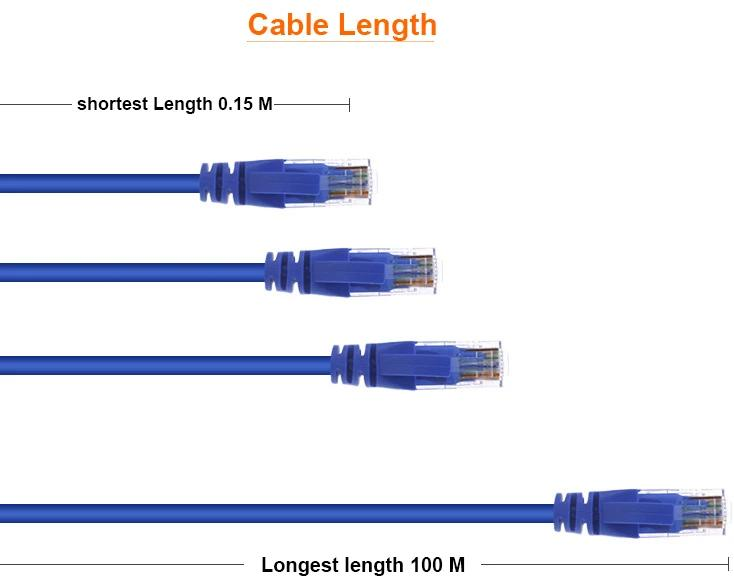
Ethernet cables are commonly used between the controller and the receiving cards. For shorter distances, this is usually a simple and reliable solution.
However, Ethernet transmission has distance limits.
As cable length increases, the quality of the cable, connectors, installation environment, and electromagnetic interference become more important. A poorly designed long cable route can increase the possibility of unstable communication.
Possible symptoms include:
Cable length is not always the cause of these problems. A damaged connector, incorrect control-system configuration, faulty receiving card, power problem, or damaged cable can create similar symptoms.
This is why cable length should be considered as part of the complete signal system.
A conventional LED wall usually has a predictable cabinet layout.
For example, receiving cards may be connected from left to right across several cabinets.
A spherical LED screen has a completely different physical structure.
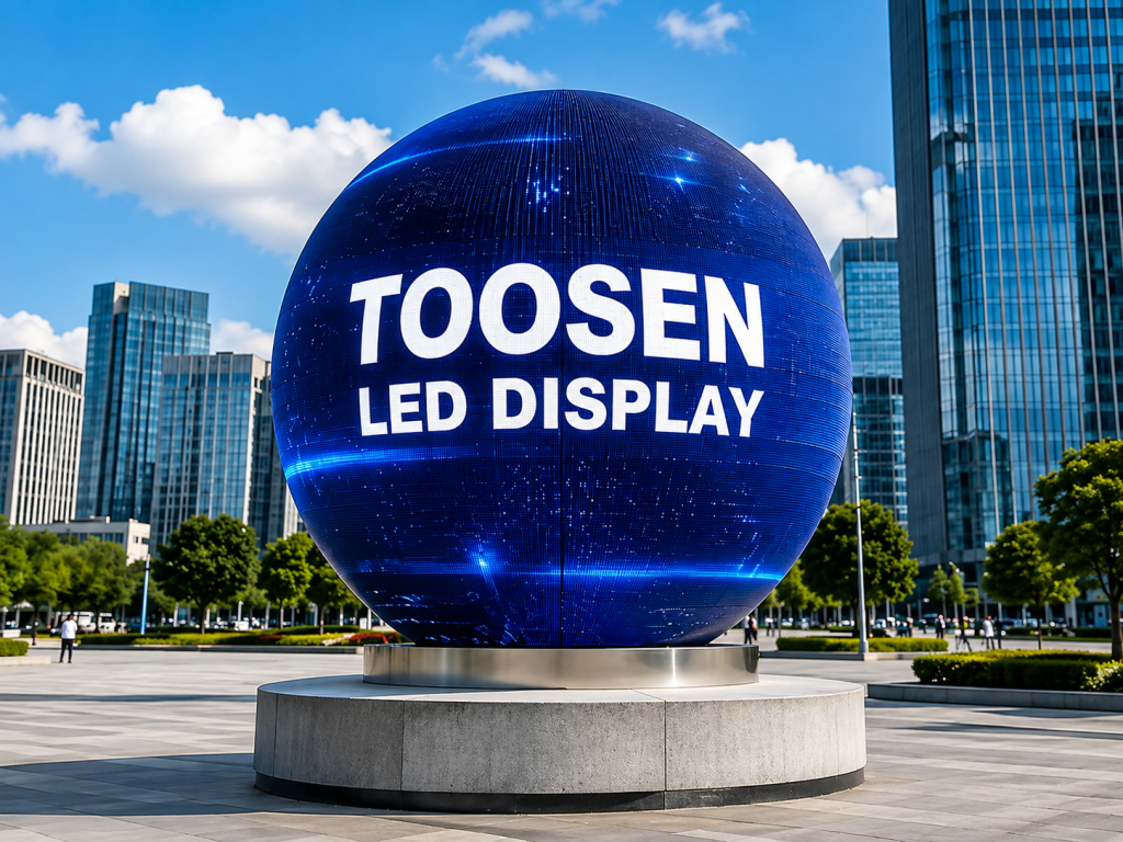
LED modules wrap around the sphere in multiple directions. Depending on the diameter and engineering design, receiving cards may be installed in different sections inside the sphere.
A large sphere might be divided into areas such as the upper hemisphere, equatorial section, lower hemisphere, or several independent signal zones.
The signal cable therefore does not always follow the shortest physical distance.
It may need to pass through the internal structure, around support frames, and between different receiving-card groups before reaching its destination.
This creates an important rule:
Physical distance is not always the same as actual cable length.
Imagine that the LED controller is located 40 meters away from the spherical LED display.
It is easy to assume that the signal transmission distance is simply 40 meters.
In practice, the complete route may include:
40 m external cable + internal routing + distribution connections
The cable may enter the sphere at one point and then continue through its internal structure before reaching the required receiving-card group.
For a small LED sphere, this additional distance may be limited.
For a large-diameter sphere, however, internal routing becomes much more important.
This is why cable planning should be completed before installation rather than after the sphere arrives at the site.
A commonly used reference for standard Ethernet copper cabling is a maximum channel length of around 100 meters under the appropriate cabling standard and installation conditions.
But there is an important difference between a theoretical maximum and a good engineering target.
Designing every project exactly at the maximum distance leaves less room for factors such as connector quality, cable condition, routing, installation workmanship, and electrical interference.
For an LED display project, engineers should therefore evaluate the complete signal route instead of simply asking:
“Is the cable shorter than 100 meters?”
A better question is:
“Is this signal path reliable for this installation environment?”
That approach becomes especially important for permanent installations and large spherical LED displays where stable long-term operation is required.
Both CAT5e and CAT6 cables are commonly seen in LED display control systems, depending on the equipment requirements.
The cable category alone, however, does not guarantee signal stability.
Cable quality, conductor quality, connectors, termination, and installation all matter.
For example, a good cable can still cause trouble if an RJ45 connector is poorly terminated. Likewise, a cable that has been sharply bent, crushed, repeatedly pulled, or damaged during installation may become a weak point in the signal chain.
When planning a spherical LED screen signal cable system, check:
These details are particularly important in installations where the signal cables must pass through a complex metal structure.
When the distance between the control room and the LED display becomes too long for the selected copper Ethernet solution, fiber optic transmission is often a better option.
A typical long-distance system may use:
Controller → Fiber Transmission → Converter/Distribution Equipment → Receiving Cards
Fiber is especially useful for large venues where the control equipment is far from the screen.
It can also be useful in environments where electrical interference is a concern because fiber carries data using light rather than electrical signals.
Possible applications include:
The exact transmission method should always match the selected controller and receiving-card system.
Cable distance is only one part of signal design.
Receiving-card topology is equally important.
Suppose a large spherical LED display has many receiving cards. Connecting all of them through one long chain may make troubleshooting more difficult and can increase the impact of a single connection failure.
A better solution for some large projects is to divide the sphere into several manageable signal zones.
For example:
Controller Port 1 → Upper Sphere Section
Controller Port 2 → Middle Sphere Section
Controller Port 3 → Lower Sphere Section
The exact layout depends on screen resolution, diameter, receiving-card capacity, controller loading, and structural design.
Signal zones can make cable routing easier and help technicians locate a problem more quickly.
For projects where signal continuity is particularly important, signal redundancy can also be considered. A backup signal route can reduce the effect of certain cable or connection failures when the selected control system supports redundancy.
Sometimes the cable itself is not the real problem.
The weak point is the connector.
LED displays are often installed in environments where cables are connected, disconnected, transported, and routed through structures. Poor termination or a loose connector can create intermittent problems that are difficult to reproduce.
The screen may operate normally for hours and suddenly show a signal problem.
When troubleshooting an unstable spherical LED display, technicians should therefore check both ends of every important signal cable instead of replacing the receiving card immediately.
For rental or frequently moved displays, connector inspection becomes even more important.
Signal planning should begin during the engineering stage.
Before production or installation, the project team should confirm the location of the controller, sphere diameter, receiving-card arrangement, internal cable route, external cable distance, and maintenance access.
For larger projects, it is also useful to identify the longest signal route.
Testing should reproduce the actual project configuration as closely as practical.
A system that works with a short test cable in the workshop does not automatically prove that the final long-distance installation will behave exactly the same way.
The final configuration should therefore be checked under realistic operating conditions before handover.
TOOSEN develops and manufactures spherical LED displays for indoor and outdoor applications.
Different sphere diameters, pixel pitches, installation methods, and control solutions can be customized according to project requirements. Instead of treating the sphere as only a creative LED shape, the engineering process should also consider signal distribution, module layout, maintenance access, structural design, and content requirements.
For large spherical LED display projects, cable routing and receiving-card distribution can be planned according to the actual sphere structure and installation environment.
This helps reduce unnecessary cable routes and makes future maintenance easier.
If your project requires a custom sphere, you can view our spherical LED display solutions and discuss the diameter, pixel pitch, control distance, installation method, and signal requirements before production.
It depends on the control system, cable type, equipment specifications, and installation environment. For standard copper Ethernet, around 100 meters is a common maximum reference, but engineers should not automatically treat the maximum value as the ideal design distance.
A properly specified CAT6 cable can be suitable for LED display signal transmission, but cable category is only one factor. Cable quality, connectors, termination, routing, interference, and total distance also affect reliability.
+86 18688923792
+86-755-23312336
4th Floor, Building B, Zhonghe Building, Taiwan Industrial Zone, 2132 Songbai Road, Shiyan Street, Bao'an District, Shenzhen.


Emall us with any questions or inquiries or use our contact data.We would be happy to answer your questions.
Toosen Professional Manufacturer of led sphere display,led screen globe,led ball display,spheric led screen,spherical led display, Led Special-shaped LED manufacturer, LED factory,Manufacturers & Suppliers,Factory & Exporters. Looking forward to your cooperation.
Copyright © 2010-2026 Toosen LED All Rights Reserved
Theme by WordPress